

Intelligent Mobile Robots Development
1.0 Background
I would like to take this opportunity to introduce an interesting project that has been ongoing for the past few years in Multimedia University. This project kind of started in 2011. Years earlier we had a small team active in applied electromagnetic research, designing modules and high-frequency electronics circuits for wireless communication and Radar systems (see another story on Synthetic Aperture Radar development). These complex systems requires an on-board computer to control and coordinate all the components, for instance one would need to turn on/off the many switches in a wireless transceiver, communicate with the phase-loop loop chip and checking its status, generate signals, perform signal sampling and processing. Thus apart from using off-the-shelf portable computer boards, we started as a side project to develop our own single-board computer (SBC). Bear in mind in 2011 the open hardware landscape and makers movement are still in the infancy. The Arduino embedded controller board is not well known yet (at least in this part of the world!), the Raspberry Pi has yet to be launched, SourceForge is still the place to go to for open source code repository, and there are not that many online blogs and videos promoting technical stuffs. Thus we decided to built our own SBC. Our first prototype SBC contains a micro-controller (MCU) running at 60 MHz and a simple custom designed real-time operating system (RTOS) to execute multiple tasks simultaneously. Out of necessity we sometimes used our SBC to control electric motors and perform feedback control tasks, and It turns out the SBC is equally adept for controlling electro-mechanical systems. A few years later when robotics and intelligent machines started to gain prominence, we figured this is an equally interesting domain to align to given our expertise in developing our own computing board and embedded systems (Note: a single-board computer is also an embedded system as the computer is ’embedded’ into the application).
2.0 The Robotic Background
2.0 The Robotic Platform
We decided to focus on mobile robots, i.e. machines that can move about autonomously, adapt to environment and achieve specific goals without supervision. One of the key challenges in robotics today is to create an autonomous machine that can navigate and adapt to unstructured or random environment (think self-driving cars). Examples of unstructured environment are outdoor environment, our home, office etc. where objects can be placed randomly and with people moving about. This is different from the robots that we find in factory or manufacturing environment, where it is assumed the location and type of objects around the robot are known a priori. We also decided to keep our initial robots small for reasons of cost (small batteries, motors and gearboxes are much cheaper), safety and ease of transportation. For instance in the case of building a robot with legs, if the machine is 1.5 meter tall and weights 30 kg, scaffolding and support would be needed keep the robot from falling over and causing damage to itself and others during developmental phase. Whereas a small legged robot weighing 1 kg or less would not need such precautions. Moreover the engineer can always carry a small robot home and continue to work on the software after office hours. Other factors that we considered are space requirement, complexity and the method of propulsion. For example flying drones require large amount of space for testing. Wheels robot with three or more wheels are too elementary (as not much real-time feedback control is needed). A two-legged robot is too complex, not only has one to contend with coordinating and controlling many motors or actuators, one also has to manage static and dynamic stability while the machine is walking. Around 2012 we stumbled upon an impressive (at that time) two-wheels self-balancing robot called nBot online. That provided the inspiration and we finally settled on the two-wheeled robotic platform. Our first prototype appeared in 2013, as shown in Figure 1, we called it the Version 0. This type of robot strikes a nice balance in complexity besides requiring small amount of space to test. A two-wheeled robot requires smaller number of actuators compare to legged robot. It also needed some form of feedback control algorithm to keep it upright during static (i.e. when the robot is remaining at one place) and dynamic (i.e. when the robot is moving around) conditions, but not to the extend of the complex algorithms required to control a walking robot. Thus the two-wheeled robotic platform allows the designer to investigate aspects such as effectiveness of the computing platform with real-time feedback control, environment sensing, high-level task planning, machine cognition and high-level behavior programming without being overwhelmed by the sheer complexity just trying to make the robot to walk in a stable manner.
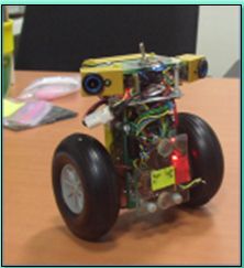
Figure 1 – The first two-wheeled robot build by us in 2013, the Version 0.
3.0 The Machines
After some delay in 2014-2015 due to other commitments of the team, we picked up the work again and right now the current iteration of our robot is called Version 2. The naming convention is based on the version of the on-board electronic system that we have developed to control our robots. We called this the Robot Controller. Thus we are now at the second generation of our Robot Controller. Figure 2 shows three examples of our two-wheeled robotic platforms. The V2P2 weights a mere 260 grams, while V2T2 is close to 1 kilogram with a pair of arms, and V2T2S is around 800 grams. Here V2T2 means “Version 2, Test build 2”, V2P2 means “Version 2, Production build 2”. Therefore the machine V2P2 is actually designed to be manufactured in higher volume. What about the suffix ‘S’ ? Well we tried a few types of electric motors to propel the robots such as brushed DC geared motor, stepper motor and brush-less DC motors. The base versions use brushed DC electric motor with gearbox, while ‘S’ denote machine using stepper motor and in future the suffix ‘B’ will denotes machine using brush-less DC motors. For now these are all small robots intended for us to perfect the hardware and software design before we can scale up to larger machines.
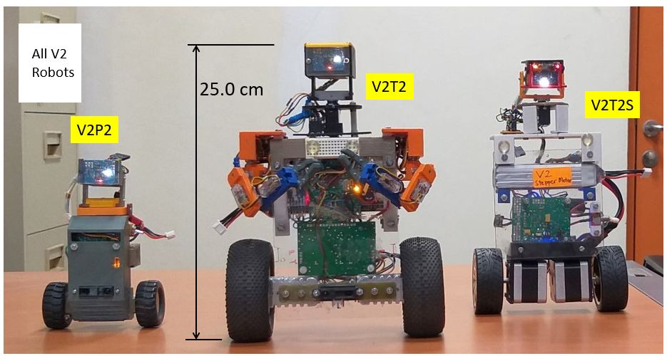
Figure 2 – Version 2 two-wheeled robot platforms, the V2P2, the V2T2, and V2T2S.
4.0 Electro-Mechanical Details
Figure 3 shows the annotated view of the V2T2, illustrating the various important parts of the robot, while Figure 4 explains the construction of the arm, or manipulator. The arm is designed to be plug-and-play, as can be seen in the rear view of Figure 3. One can design a few variation of the manipulators, keeping to the weight and power consumption constraints and just swap the manipulators as needed.
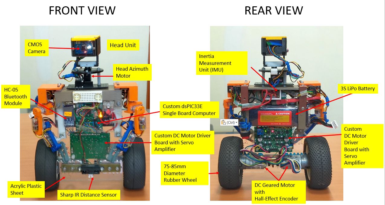
Figure 3 – Front and rear views of V2T2.
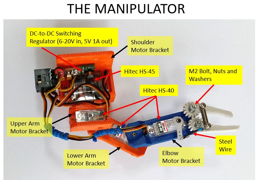
Figure 4 – The 4 DOF (degree-of-freedom) manipulator installed on V2T2.
5.0 The Control Hierarchy and Videos
Our initial prototype has only one processor to handle all the tasks of driving the motors, processing the sensors outputs, running a digital feedback control algorithm, handling the wireless communication with a remote computer down to high-level task planning. The processor on the Robot Controller soon runs out of bandwidth with all these requirements. There are a few options to meet the higher demand in computing power: 1) By upgrading to a more power processor 2) Using multiple processors working in parallel 3) Hybrid, i.e. upgrading and using multiple processors. In Option (2) and (3), one can also use a processor with multiple cores. Our latest iteration employs the strategy of Option (3), with three separate processor chips. This is best illustrated by looking at the tear down of the V2P2 robot in Figure 5, with the control hierachy shown in Figure 6. The advantage of using three separate circuit boards for three processors, as opposed to using a single multi-core processor is this allows the flexibility of changing each processor board without affecting other aspects of the design.
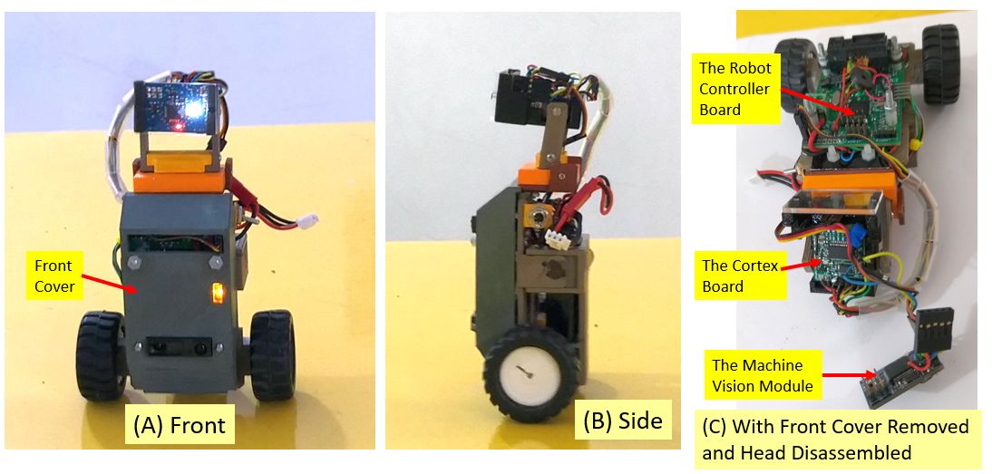
Figure 5 – Closed-up view of V2P2, (A) Front, (B) Side (C) The robot lying down with the front cover removed to reveal the Robot Controller board.
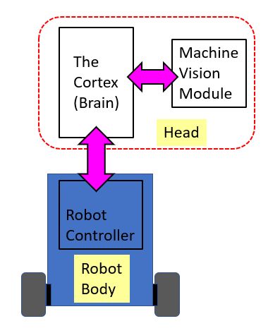
Figure 6 – The control hierarchy.
Here the V2P2 has one processor (e.g. the micro-controller) in the robot body for running low-level and time-critical routines such as the digital feedback control algorithms to keep the robot balance upright, movement (e.g. turning, moving forward/backward) control and processing all the sensors signals on the robot body. The ‘Head’ unit on the V2P2 contains two processors. One is dedicated to the camera on-board the head, running video processing algorithms to make sense of the environment through visual input. We call this the Machine-Vision Module (MVM). The other processor on the head, which we dub the Cortex (the cortex in neuroscience refers to the outer layer of the mammalian brain, which perform all high-level and abstract thinking). The Cortex interfaces with both the processors in the robot body and the MVM, performing high-level tasks. The link below features an initial result of the V2P2 navigating in an unstructured environment, avoiding obstacles and at the same time searching for a yellow tennis ball.
Here is another link to an older video, showing both V2T2 and an early version of V2P2 tracking the same tennis ball with their heads.
6.0 Future Plans
Plans are currently under way to scale up the design to robots of more practical size in 2020 and beyond. Currently we are experimenting with 250 W brush-less DC motor drives, and also in the process of developing the third generation electronic systems for the Robot Controller. A larger version of the robotic platform, presently codenamed V3T1, standing between 50 to 60 cm tall and weighing in at 5 kg is expected to be rolled out at Q2 of 2020. An artist impression is shown in Figure 7.
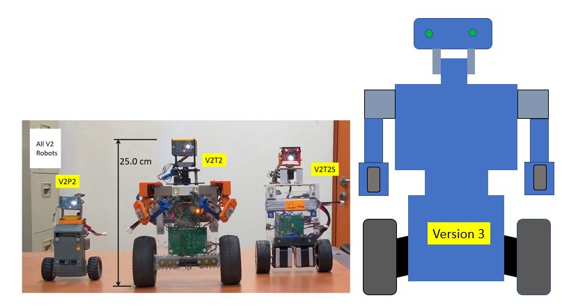
Figure 7 – The projected size of Version 3.

Fabian Kung received his B.Eng (Hons) and M.EngSc in Electrical Engineering from University Malaya, Malaysia in 1994 and 1998 respectively. He later obtained his PhD in Electrical Engineering from Multimedia University (MMU) in 2003. He worked as PCB design engineer with Intel Microelectronics Sdn Bhd (Penang) from 1994-1996, and subsequently as embedded system design engineer with GMS Technologies Sdn Bhd (Selangor) from 1997 to 1999. He joined MMU as a faculty member in 1999 and currently holds the position of Professor. His area of interests are analog electronics, applied electromagnetics, RF/Microwave circuit design, embedded systems and robotics. He has many years of experience in hardware and software development.